 |
Cybertelecom Federal Internet Law & Policy An Educational Project |

|
Internet over Powerline / BPL |  |
|
- Powerlines - Regulatory Proceedings - - United Powerline - - United Telecom's - - Part 15 Amendments - - BPL Notice of Inquiry - Reference - Broadband - Sec. 706 - Stimulus Plan - Natl BB Map - FCC Natl BB Plan - Dial Up - DSL - - Naked DSL - - UNE - - Net over Wireline (Info Service) - Cable - - Open Access - Fiber - Wireless - - 3G - - Wifi - - WiMax - - 700 Mhz - Powerline - Satellite - Muni Broadband - Telecom Services - Computer Inquiries - Network Neutrality - Forbearance - Backbones - - ICAIS - Layers - Interconnection - - Negotiation - Reciprocal Comp - Mergers - Federal Advisory Committees - FCC - NTIA - Universal Service - Statistics: Broadband |
Derived From: Potential Interference from Broadband over Power Line (BPL) Systems to Federal Government Radio Communications at 1.7 - 80 MHz - Phase I Study, NTIA (2004)
SECTION 2 TECHNICAL DESCRIPTION OF BPL SYSTEMS
2.1 INTRODUCTION
 |
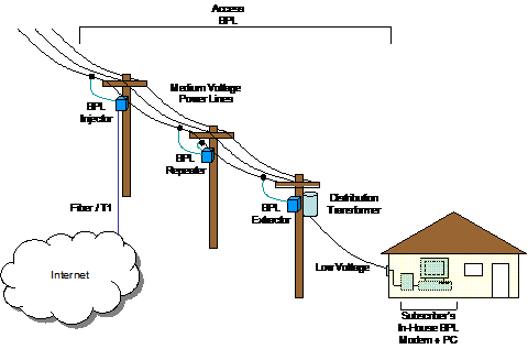
Access BPL equipment consists of injectors (also known as concentrators), repeaters, and extractors. BPL injectors are tied to the Internet backbone via fiber or T1 lines and interface to the Medium Voltage (MV) power lines feeding the BPL service area. MV power lines may be overhead on utility poles or underground in buried conduit. Overhead wiring is attached to utility poles that are typically 10 meters above the ground. Three phase wiring generally comprises an MV distribution circuit running from a substation, and these wires may be physically oriented on the utility pole in a number of configurations ( e.g. , horizontal, vertical, or triangular). This physical orientation may change from one pole to the next. One or more phase lines may branch out from the three phase lines to serve a number of customers. A grounded neutral conductor is generally located below the phase conductors and runs between distribution transformers that provide Low Voltage (LV) electric power for customer use. In theory, BPL signals may be injected onto MV power lines between two phase conductors, between a phase conductor and the neutral conductor, or onto a single phase or neutral conductor.
Extractors provide the interface between the MV power lines carrying BPL signals and the households within the service area. BPL extractors are usually located at each LV distribution transformer feeding a group of homes. Some extractors boost BPL signal strength sufficiently to allow transmission through LV transformers and others relay the BPL signal around the transformers via couplers on the proximate MV and LV power lines. Other kinds of extractors interface with non-BPL devices ( e.g. , WiFiT) that extend the BPL network to the customers' premises.
For long runs of MV power lines, signal attenuation or distortion through the power line may lead BPL service providers to employ repeaters to maintain the required BPL signal strength and fidelity. Figure 2-1 illustrates the basic BPL system, which can be deployed in cell-like fashion over a large area served by existing MV power lines.
2.2 BPL System Architectures
NTIA identified three different network architectures used by BPL equipment vendors. These architectures are described below.
2.2.1 System #1
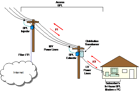
System #1 (see Figure 2-2) employs Orthogonal Frequency Division Multiplexing (OFDM) to distribute the BPL signal over a wide bandwidth using many narrow-band sub-carriers. At the BPL injector, data from the Internet backbone is converted into the OFDM signal format and is then coupled onto one phase of the MV power line. An injector also converts BPL signals on the MV power lines to the format used at the Internet backbone connection. The two-way data are transferred to and from the LV lines, each feeding a cluster of homes, using BPL extractors to bypass the LV distribution transformers. The extractor routes data and converts between access and in-house BPL signal formats. The subscribers access this BPL signal using in-house BPL devices. To span large distances between a BPL injector and the extractors it serves, repeaters may be employed.
 |
The System #1 injector and extractors share a common frequency band (F1) on the MV power lines, different than the frequency band (F2) used on the LV lines by the subscriber's in-house BPL devices. In order to minimize contention for the channel, Carrier Sense Multiple Access (CSMA) is used with Collision Avoidance (CA) extensions. This type of system is designed to accept some amount of co-channel interference between quasi-independent BPL cells without the use of isolation filters on the power lines, as all devices on the MV lines operate over the same frequency band. The BPL signal may be sufficiently tolerant of co-channel BPL interference to enable implementation of two or three of these systems independently on adjacent MV power lines. System #1 couples BPL signals into one phase line.
2.2.2 System #2
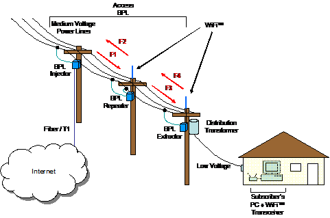
System #2 also uses OFDM as its modulation scheme, but differs from System #1 in the way it delivers the BPL signal to the subscribers' homes. Instead of using a device that uses LV power lines, System #2 extracts the BPL signal from the MV power line and converts it into an IEEE 802.11b WiFiT signal for a wireless interface to subscribers' home computers as well as local portable computers (see Figure 2-3). Technologies other than WiFiT might also be used to interface to subscribers' devices with the BPL network, the important point being that BPL is not used on LV power lines in System #2.
 |
This system uses different radio frequency bands to separate upstream (from the user) and downstream (to the user) BPL signals, and to minimize co-channel interference with other nearby access BPL devices. To span large distances between a BPL injector and the extractors it serves, repeaters may be employed. Like the injectors, BPL repeaters transmit and receive on different frequencies, and they use different frequencies from those used by the injector and other nearby repeaters. System #2 repeaters may also provide the capabilities of an extractor when outfitted with a WiFiT transceiver. System #2 couples BPL signals onto one phase of the MV power line.
2.2.3 System #3
System #3 uses Direct Sequence Spread Spectrum (DSSS) to transmit the BPL data over the MV power lines. All users within a BPL cell share a common frequency band. In order to minimize contention for the channel, Carrier Sense Multiple Access (CSMA) is used. Like System #1, this type of system is designed to accept some amount of co-channel interference between cells, as all devices operate over the same frequency band. At one trial deployment of the System #3 architecture, the BPL service provider independently implements two phases of the same run of three phase power lines.
Each cell in System #3 (see Figure 2-4) is comprised of a concentrator (injector) that provides an interface to a T1 or fiber link to the Internet backbone, a number of repeaters (extractors) to make up for signal losses in the electric power line and through the distribution transformers feeding clusters of dwellings, and customer premises BPL equipment, used to bridge between the user's computer and the electrical wiring carrying the BPL signal. Adjacent cells typically overlap and the customers' BPL terminals and repeaters are able to communicate with the concentrator that affords the best communication path at any time.
System #3 couples the BPL signal onto the power line using a pair of couplers on a phase and neutral line.
2.3 POTENTIAL FUTURE SYSTEMS
BPL manufacturers and service providers anticipate a wide range of applications that may be offered to their subscribers. High quality, multi-channel video, audio, voice over Internet Protocol (VoIP), and on-line gaming applications are expected to rapidly increase the demand for additional bandwidth. [8] To support the typical subscriber at 1 Mbps, BPL systems are expected to operate at speeds of 100 Mbps or more on the MV power lines in the near future. A number of comments filed in response to the NOI indicate that the BPL industry is already preparing for this growth. [9]
A number of BPL vendors have suggested use of frequencies up to 50 MHz. [10] At least one vendor is considering use of 4 MHz to 130 MHz, while excluding frequencies that are actively in use by certain licensed services. [11] One solution put forward in an attempt to mitigate interference with licensed services is to attenuate or "notch" BPL signals in frequency bands where licensed services are in nearby use. [12] Future BPL systems may be able to accomplish this automatically without system operator intervention. To implement this solution while simultaneously maximizing the useable bandwidth, BPL systems are expected to use new modulations that can support more sub-carriers that are more finely spaced. [13]
As data rates and bandwidth requirements grow, the BPL systems may require operation at greater transmitted power levels but not necessarily with higher power density than is used today. BPL vendors may employ techniques to dynamically adjust the power level to maintain a minimum signal-to-noise ratio (SNR) over the entire BPL spectrum, while limiting emissions to levels compliant with Part 15. One vendor has proposed such a solution for adjusting transmitted power to maintain a constant SNR across the BPL spectrum, with a hard limit based on Part 15 rules. [14] The challenge will be to develop the control mechanism that can maximize transmitted power while simultaneously limiting the radiated emissions, perhaps in conjunction with frequency agility.
Nortel has developed and patented a filter that blocks BPL signals while concurrently passing medium-voltage AC power. The judicious use of such blocking filters will enable optimal segmentation of BPL networks into cells of various sizes having low conducted co-channel interference from neighboring cells. This will enable a greater level of frequency reuse than what is currently available. [15]
Another BPL technology utilizes the 2.4 GHz and 5.8 GHz unlicensed bands. [16] An implementation using multiple IEEE 802.11b/g WiFiT chips sets has been used to demonstrate the concept of carrying data over medium-voltage power lines at rates exceeding 200 Mbps. However, no party filed comments contending that this technology and these frequencies should be considered in the BPL proceedings.
2.4 SUMMARY
Three architectures for access BPL networks were identified: (1) BPL systems using different frequencies on medium- and low-voltage power lines for networking within a neighborhood and extensions to users' premises, respectively; (2) BPL use of only medium voltage lines for networking within a neighborhood, with other technologies being used for network extensions to users' premises; and (3) BPL use of the same frequencies on medium- and low-voltage power lines for networking in a neighborhood and extensions to users' premises. BPL systems currently provide data rates ranging from 1 Mbps to 10 Mbps, and operate at frequencies between 2 MHz and 50 MHz. In the future, BPL systems will operate at data rates exceeding 100 Mbps, utilizing greater bandwidth and/or advanced modulation schemes. BPL equipment vendors may employ additional signal processing techniques to optimize performance while simultaneously limiting emissions to Part 15 levels.
[6] MV lines, typically carrying 1,000 to 40,000 volts, bring power from an electrical substation to a residential neighborhood. Low Voltage distribution transformers step down the line voltage to 220/110 volts for residential use. See BPL Inquiry at ¶ 13.
[7] A degree of coupling occurs between BPL signals on adjacent phases.
[8] Comments of HomePlug Powerline Alliance , BPL Inquiry, July 7, 2003 ("HPA Comments") at 3-5.
[9] Comments of PowerWAN, Inc., BPL Inquiry, July 3, 2003 , ("PowerWAN Comments") at 2; Comments of Main.net Communications, Ltd., BPL Inquiry, July 7, 2003 ("Main.net Comments") at 3.
[10] PowerWAN Comments at 2; Comments of Amperion, Inc., BPL Inquiry, July 7, 2003 , ("Amperion Comments") at 4.
[11] Reply Comments of PowerComm Systems, Inc., BPL Inquiry, August 20, 2003 , ("PowerComm Reply Comments") at 14.
[12] Main.Net Comments at 7; Comments of Ambient Corporation, BPL Inquiry, July 7, 2003 , ("Ambient Comments") at 8; PowerWAN Comments at 3.
[13] PowerComm Reply Comments at 17.
[14] Ambient Comments at 6-7.
[15] System, device, and method for isolating signaling environments in a power line communication system , United States Patent No. 6,590,493, Rasimas, et al., July 8, 2003 .
[16] Corridor Systems Announces Breakthrough Technology For Broadband Over Powerlines (BPL), Demonstrates 216Mbps over PG&E's Medium-Voltage Grid , Santa Rosa, CA, September 22, 2003 http://www.corridor.biz/0309-corridor-pr.pdf .